

It is also known as spark erosion machining or spark machining. The material of workpiece removed due to erosion caused by an electric spark. The material is removed from the workpiece by a series of rapidly recurring current discharges between two electrodes, separated by a dielectric liquid and subject to an electric voltage.
Working Principle of Electric Discharge Machining
Electric discharge machining process is carried out in presence of dielectric fluid which creates a path for discharge. When a potential difference is created across the two surfaces of die-electric fluid, it gets ionized. An electric spark/discharge is generated across the two terminals. The potential difference is developed by a pulsating direct current power supply connected to the two terminals. One of the terminals is positive terminal given to workpiece and tool is made negative terminal. Two third of the total heat generated is generated at the positive terminal so workpiece is generally givenpositive polarity. The discharge develops at the location where two terminals are very close. When the voltage between the two electrodes is increased, the intensity of the electric field in the volume between the electrodes becomes greater than the strength of the dielectric (at least in some places), which breaks down, allowing current to flow between the two electrodes. This phenomenon is the same as the breakdown of a capacitor (condenser). As a result, the material is removed from the electrode. So tool helps in focusing the discharge or intensity of generated heat at the point of metal removal, this way two metal is melted and evaporated.
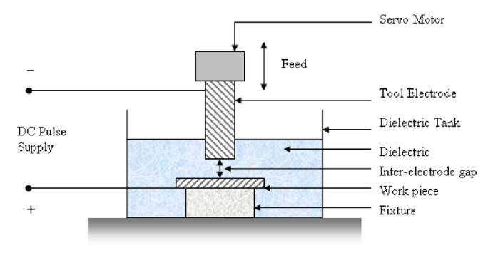
Base and Container
A container of non-conducting, transparent material is used for carrying out EDM. The container is filled with dielectric solution. A base to keep workpiece is installed at the bottom of the container. The base is made of conducting material and given positive polarity.
Tool
The tool is given negative polarity. It is made of electrically conducting material line brass, copper or tungsten. The tool material selected should be easy to machine, high wear resistant. The tool is made slightly undersized for inside machining and oversized for cut side machining. The tool is designed and manufactured according to the geometry to be machined.
Dielectric Solution
The dielectric solution is a liquid which should be electrically conductive. This solution provides two main functions, firstly it drives away the chips and prevents their sticking to workpiece and tool. It enhances the intensity of discharge after getting ionized and so accelerates metal removal rate.
Power Supply
A DC power supply is used, 50 V to 450 V is applied. Due to ionization of dielectric solution an electrical breakdown occurs. The electric discharge so caused directly impinges on the surface of the workpiece. It takes only a few microseconds to complete the cycle and remove the material. The circuit can be adjusted for auto off after pre-decided time interval.
Tool Feed Mechanism
In case of EDM, feeding the tool means controlling a gap between the workpiece and the tool. This gap is maintained and controlled with the help of servo mechanism. To maintain a constant gap throughout the operation tool is moved towards the machining zone very slowly. The movement speed is towards the machining zone very slowly. The movement speed is maintained by the help of gear and rack and pinion arrangement. The servo system senses the change in the gap due to metal removal and immediately corrects it by moving the tool accordingly. The spark gap normally varies from 0.005 mm to 0.50 mm.
Workpiece and Machined Geometry
The important point for the workpiece is that any material which is electrical conductor can be machined through this process, whatever be the hardness of the same. The geometry which is to be machined into the workpiece decides the shape and size of the tool.
HIGHLIGHTS
- Tool material: Cu, Brass, Cu-W Alloy, Ag-W-Alloy, Graphite.
- Wear Ratio: 0.1 to 10.
- Maximum material removal rate (MRR) is 5× 103 mm3/min.
- The gap between workpiece and tool is 10 to 125 µm.
- Servo control: Electrohydraulic
- Wear Ratio = Volume of work material removed / Volume of electrode consumed
- MRR = 2.4 / (melting point 0C)1.25
- Temperature between 8000 C and 12000 C at the point of discharge.
Advantages of EDM
- Complex shapes that would otherwise be difficult to produce with conventional cutting tools.
- Extremely hard material to very close tolerances.
- Very small workpieces where conventional cutting tools may damage the part from excess cutting tool pressure.
- There is no direct contact between tool and workpiece. Therefore, delicate sections and weak materials can be machined without perceivable distortion.
- A good surface finish can be obtained; a very good surface may be obtained by redundant finishing paths.
- Very fine holes can be attained.
- Tapered holes may be produced.
- This process is very much economical for machining very hard material.
- Maintains a high degree of dimensional accuracy so it is recommended for tool and die making.
- Complicated geometries can be produced which are very difficult otherwise.
- Appreciably high value of MRRR can be achieved as compared to other non-conventional machining processes.
Disadvantages and Limitations of EDM Process
- The slow rate of material removal.
- Potential fire hazard associated with the use of combustible oil based dielectrics.
- The additional time and cost used for creating electrodes for ram/sinker EDM.
- Reproducing sharp corners on the workpiece is difficult due to electrode wear.
- Specific power consumption is very high.
- “Overcut” is formed.
- Excessive tool wear occurs during machining.
- Electrically non-conductive materials can be machined only with the specific set-up of the process.
- This process cannot be applied to very large sized workpieces as the size of the workpiece is constrained by the size of set up.
- Due to the application of very high temperature at the machining zone, there are chances of distortion.
- EDM process is not capable to produce sharp corners.
- MRR achieved in EDM process is considerably lower than the MRR in case of conventional machining process so it cannot be taken as an alternative to a conventional manufacturing process.
